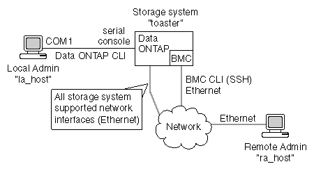


The Baseboard Management Controller (BMC) is a remote management device that is built into the motherboard of the FAS2000 series storage systems. It provides remote platform management capabilities, including remote access, monitoring, troubleshooting, logging, and alerting features.
The BMC firmware supports Intelligent Platform Management Interface (IPMI) version 2.0, which by default supports Serial Over LAN (SOL) for console redirection.
The BMC stays operational regardless of the operating state of the storage system. Both the BMC and its dedicated Ethernet NIC use a standby voltage for high availability. The BMC is available as long as the storage system has input power to at least one of the storage system’s power supplies.
The BMC monitors environmental sensors, including sensors for the temperature of the system's non-volatile memory (NVMEM) battery, motherboard, and CPU, and for the system's voltage level. When the BMC detects that an environmental sensor has reached a critically low or critically high state, it generates AutoSupport messages and shuts down the storage system. The data generated by the sensors can be used as a reference point to help you troubleshoot storage system issues. For example, it can help a remote system administrator determine if a system was shut down due to an extreme temperature change in the system.
The BMC also monitors non-environmental sensors for the status of the BIOS, power, CPU, and serial-attached SCSI (SAS) disks. These sensors are recorded by the BMC to assist support personnel.
The following table lists the names and the description of the sensors that BMC monitors:
| Sensor Name | Description |
|---|---|
| 1.1V | Board 1.1V sensor |
| 1.2V | Board 1.2V sensor |
| 1.5V | Board 1.5V sensor |
| 1.8V | Board 1.8V sensor |
| 2.5V | Board 2.5V sensor |
| 3.3V | Board 3.3V sensor |
| CPU 1.2V | CPU 1.2V sensor |
| 12.0V | Power 12V sensor |
| BIOS Status | BIOS status normal |
| Board Temp Top | Temperature at the top side of the board |
| Board Temp Bot | Temperature at the bottom side of the board |
| CPU Status | CPU status OK |
| CPU Temp | CPU temperature |
| Power Status | Power on/off |
| Batt Amp | Battery amp |
| Batt Capacity | Battery capacity |
| Charger Amp | Battery charge amp |
| Charger Cycles | Battery charge cycle |
| Charger Volt | Battery charge voltage |
| Batt Temp | Battery temperature |
| Batt Run Time | Battery run time |
| Batt 8.0V | Battery 8.0 voltage |
| NVMEM 1.8V | NVMEM 1.8 voltage |
| NVMEM 8.0V | NVMEM 8.0 voltage |
| SAS Status | SAS status OK |

You use the BMC CLI to monitor and troubleshoot the storage system.
You use the Data ONTAP CLI to administer the storage system and the BMC.
If you have a data center configuration where management traffic and data traffic are on separate networks, you can configure the BMC on the management network.